
What made to drawing covers
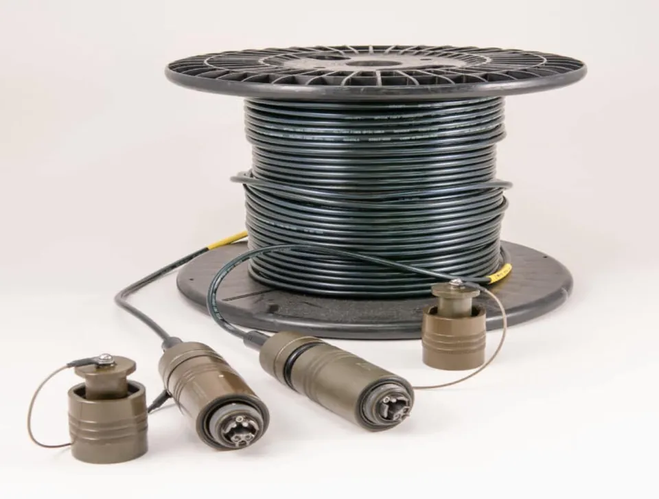
Most assemblies that leave the Radix floor are custom fibre optic assemblies: a breakout that is not catalogued, a jacket specified for one site, or a channel count that does not exist as a standard part. The drawing or BOM controls these variables:
- Length overall and per leg, with tolerance.
- Fibre count and type, single-mode or multimode, glass, PCF or plastic optical fibre.
- Connectors at every end, including polish and gender.
- Polarity and the fibre-to-position map.
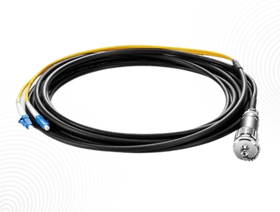
- Breakout position, leg construction and stagger.
- Jacket material, fire rating, colour and any armour.
- Marking on the cable and labels at each end.
Custom assemblies by industry
| Industry | Typical custom assembly | What drives the design |
|---|---|---|
| Data centre and enterprise | MPO trunks cut to measured routes, MPO to LC breakouts, conversion harnesses | Density, polarity, loss budget |
| Broadcast and live production | SMPTE hybrid camera cables, fibre and SDI runs, opticalCON assemblies | Mating cycles, strain relief, length per venue |
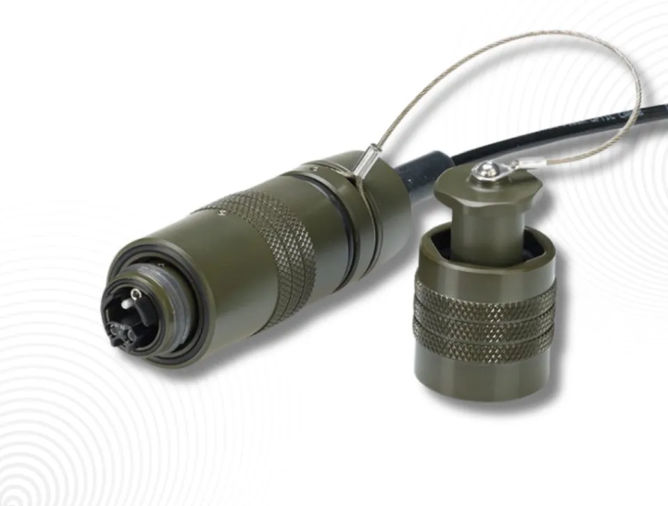
| Defence and aerospace | Mil-aero assemblies and harnesses to platform drawings, tactical reels | Connector standard, sealing, shielding, handling |
| Energy, offshore and utilities | Sealed MIL and ODC assemblies, Harting-housing LC panel leads, PCF links | Ingress rating, salt, EMI immunity |
| Industrial, medical and sensing | POF HFBR and TOCP 200 links, SMA laser delivery and sensor assemblies | Coupling face, vibration, heat |
Each environment is covered in more detail on the industries page.
From drawing and BOM to quote
The process follows four steps.
- Requirement. The application, environment and performance target are recorded, along with the standard the installation is held to.
- Design. Fibre, connector, jacket, strain relief and minimum bend radius are specified against the drawing and confirmed in writing. Questions about gaps or conflicts in the drawing are raised here.
- Manufacture. Assemblies are built and terminated in the Pune facility, then tested for insertion loss, return loss and continuity per channel.
- Delivery. Assemblies are labelled, reeled or coiled to the order, with the test report included.
The written design confirmation is the step that prevents most disputes. If the confirmed design differs from what you expected, it is cheap to change at that point and expensive afterwards.
What a good drawing contains
A drawing does not need to be elaborate. It needs to be unambiguous.
- A sketch of the assembly with every end labelled, and lengths dimensioned from a stated reference point.
- A connector table: end label, connector type, polish, gender, and any approved part number.
- A fibre map: which fibre goes to which position at each end, with transmit and receive identified.
- Cable specification: fibre type, count, jacket, outer diameter limit and any armour.
- Label and marking text, and where it sits.
- Test requirements and acceptance limits.
The RFQ guide for fibre assemblies includes a checklist. For multi-branch builds, see harnesses and optical systems.
BOM: approved parts or equivalents
If the BOM names specific connector or cable part numbers, state whether they are mandatory or whether equivalents are acceptable. Platform and defence drawings often require the named part. Commercial projects often allow equivalents that meet the same specification. Saying which applies avoids a quote built on the wrong assumption.
State the loss target as a maximum per mated pair or per assembly, and check it against the channel with the fibre loss budget calculator before fixing it on the drawing.
Why custom assemblies fail in service
Field failures in custom assemblies usually trace back to the specification rather than to the termination. The common causes are predictable.
- Bend radius at the boot. The cable leaves the connector into a tight bend because the enclosure is shallower than the drawing assumed. Give the space available behind each connector.
- Legs too short. Breakout legs that cannot reach the far port without tension. Dimension each leg to its port.
- Wrong connector for the location. An unsealed connector at a wet or dusty end. State the environment at each end as well as along the run.
- Strain relief that does not match the use. A rack-grade boot on a cable that is flexed every day.
- Labels that do not match records. Correct assemblies installed in the wrong place. Supply the label text from your own documentation.
First article and repeat orders
For a new design, ask whether a first article can be built and approved before the full quantity. Once approved, the drawing revision becomes the reference for repeat orders, and lot and batch identification is recorded against each order. When the drawing changes, issue a new revision rather than describing the change in an email, so the build record and the drawing agree.
Send the drawing, BOM and quantities through the request a quote page.
Questions buyers ask
Do I need a formal drawing to order a custom assembly?
No. A clear sketch with lengths, connectors at each end, fibre type and count, and the fibre map is enough to start. The design is then confirmed in writing before manufacture.
Can you build to our approved part numbers?
Yes, when the BOM names them. State whether the named parts are mandatory or whether equivalents meeting the same specification are acceptable.
What testing is done on custom assemblies?
Each channel is tested for insertion loss, return loss and continuity, and the report ships with the order. If you need a particular report format or acceptance limit, include it with the drawing.
Can a custom assembly combine fibre and copper?
Yes, where the application calls for it, for example hybrid broadcast camera cables that carry fibre with power and control conductors. Show both on the drawing.
How do repeat orders work?
The approved drawing revision becomes the reference. Quote the part number and revision on each repeat order, and issue a new revision for any change.