Range
MTP MPO cable assemblies
Trunks, patch cords, breakouts and conversion harnesses, built in Pune to the fibre count, polarity and length on your drawing.
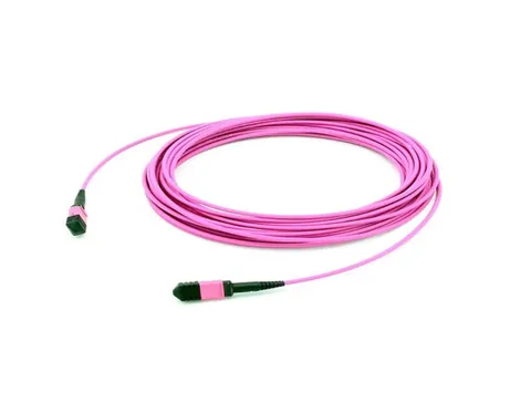
Click the photo to enlarge. Illustrative photo of a Radix assembly; yours is built to your specification.
How 48-fibre OM3 MTP assemblies are laid out, what they can carry, and what a drawing needs before you ask for a quote.
A 48-fibre MTP OM3 assembly carries forty-eight 50/125 micron OM3 fibres, usually split into four 12-fibre MTP legs at each end. OM3 reaches 300 m at 10G and 100 m at 40G, but only 70 m at 100G SR4. Polarity, gender and leg lengths must be drawn out. Send the drawing and Radix replies with what it can build.
| Assemblies needed (4 links each) | 12 / 4 |
|---|---|
| Fibres installed | 3 x 48 |
| Fibres lit | 12 links x 8 |
| Fibres dark | 144 minus 96 |
| Cable loss, OM3 | 0.06 km x 3.5 dB/km |
| Mated MTP pairs (assumed 0.35 dB each, two in the channel) | 2 x 0.35 dB |
| Channel loss | 0.21 + 0.70 |
| Margin | 1.9 minus 0.91 |
Radix confirms the exact build, fibre grade and test figures in your quote. Made to order, so lengths, connectors and labelling follow your drawing.
OM3 is laser-optimised 50/125 micron multimode fibre with an effective modal bandwidth of 2000 MHz.km at 850 nm. Maximum attenuation is 3.5 dB/km at 850 nm. Those numbers set the reach of each parallel interface, as listed in IEEE 802.3.
| Interface | Fibres used | OM3 reach | OM4 reach for comparison |
|---|---|---|---|
| 10GBASE-SR | 2 | 300 m | 400 m |
| 40GBASE-SR4 | 8 | 100 m | 150 m |
| 100GBASE-SR10 | 20 | 100 m | 150 m |
| 100GBASE-SR4 | 8 | 70 m | 100 m |
| 400GBASE-SR8 | 16 | 70 m | 100 m |
OM3 therefore suits 10G and 40G links of up to 100 m, and rows of racks within a single hall. For 100G and above, the OM3 reach falls to 70 m, and OM4 is the better grade for any run near that limit. The grades are compared in the OM3, OM4 and OM5 guide, and there is a ready-made comparison of OM3 for the 25G case in OM3 vs OM4 for 25G.
Radix builds this to your drawing in Pune and quotes by form, phone or WhatsApp. An engineer reads every request.
Send us:
Add this item to your list, add more items, then send one request.
A 48-fibre MTP OM3 assembly carries forty-eight 50/125 micron multimode fibres of OM3 grade between two points, ending in MTP connectors at each end. No common single connector holds 48 fibres, so the assembly is built from several connectors. The usual layout is one 48-fibre cable that splits at each end into four 12-fibre legs, each ending in an MTP-12. Another layout uses two 24-fibre legs and two MTP-24 connectors per end. The right layout depends on the equipment ports at each end, so it starts with the drawing and not with the fibre count.
This page is buyer education for these assemblies: how the layouts differ, what OM3 can and cannot carry, how to work out polarity and leg lengths, and what to put in an enquiry. Radix builds fibre assemblies to the buyer's drawing in Pune. For a 48-fibre OM3 build, send the drawing and the reply states what can be built. For the product family, see MTP and MPO cables, and for the related page on the product itself, see MTP OM3 48F patch cords.
| Layout | Connectors per end | Lit fibres in common use | Used for |
|---|---|---|---|
| 4 x MTP-12 on a 48-fibre cable | 4 | 8 of 12 per leg for 40G-SR4 or 100G-SR4, so 32 of 48 | Four parallel optic ports from one cable run |
| 4 x MTP-12 with 10G duplex breakout at the far end | 4 at one end, LC legs at the other | All 48 fibres, as 24 duplex pairs | Feeding 24 10G-SR ports from one trunk |
| 2 x MTP-24 on a 48-fibre cable | 2 | 20 of 24 per leg for 100G-SR10, so 40 of 48 | Two 100G-SR10 ports (older design) |
| 4 x MTP-12 to a cassette bank | 4 | All 48 through cassettes | Patch-panel trunks for structured cabling |
The count of lit fibres matters for cost. A 40G-SR4 port uses fibres 1 to 4 and 9 to 12 of the 12 (eight in total) and leaves the four middle fibres dark. Four such ports on a 48-fibre cable leave 16 fibres unused. If your design is all 40G, a base-8 cabling plan may suit better, with the cost of a plan that is specific to 40G. The comparison is explained in MTP-24 vs two MTP-12, and the 40G fibre usage is in 40G SR4 and BiDi cabling.
Parallel optics send light on four fibres and receive on four others, so the cable has to flip the fibre positions between ends. In the TIA polarity scheme the usual method for this is Type B, where fibre position 1 at one end lands at position 12 at the other and the connector keys sit on opposite sides (key-up to key-down). Each of the four 12-fibre legs in a 48-fibre assembly has its own polarity, and all four must follow the same method or a link in the middle of the set will not light.
The full set of rules is in the MPO polarity guide, and the cassette wiring maps are in MPO polarity in cassettes. A fibre polarity test is the cheap way to confirm the build, as described in fibre polarity testing.
The cable splits into legs at a furcation body, and the legs carry the connectors. The leg design affects installation more than the fibre does.
| Choice | Options | What to think about |
|---|---|---|
| Leg length | Equal, or staggered in steps | Staggered lengths keep the four connectors from bunching at the port, and let the legs reach different ports in a panel |
| Leg construction | Individual jacketed legs of 12 fibres, or a bundle with a shared sleeve | Individual legs are easier to route; bundles are tidier but less flexible |
| Pulling | Protected ends, a pulling eye, or a sock | Four connectors on a 48-fibre cable are hard to pull through a duct without protection |
| Cable outside diameter | Set by the 48-fibre cable design | Bigger cable means a bigger bend radius; check the data sheet |
| Labels | Leg number, end, polarity, fibre count | Print on each leg and on the furcation body |
The leg lengths and types are examined in MPO fanout lengths and leg types. For pulling and bends in a duct, use the MPO bend radius and pulling tension guide, and do not exceed the limits on the data sheet of the cable you are quoted.
The numbers are assumed for illustration. A design needs 12 links of 40G-SR4 between a leaf row and a spine row, 60 m by cable route. Each link is one 12-fibre MTP with eight lit fibres.
The channel passes. The connector value is the part to question: a standard-loss MPO may be rated at 0.5 dB or more per pair, which would give 1.21 dB and still pass. Adding a patch panel with another pair of connectors on each side doubles the connector loss and leaves little margin. The method is in the fibre loss budget guide. The 33 per cent dark-fibre figure is also a cost to weigh. If every port is 40G for the life of the cable, an eight-fibre plan removes the waste, whereas 48-fibre cabling pays off when the same cable may be re-used for duplex 10G, which lights all 48 fibres.
OM3 makes sense when the equipment is already OM3-cabled, when the rack is a copy of an existing one, or when channels are short and the speed will not rise. It is a poor choice for a long-term backbone: a grade that gives 100 m at 40G gives only 70 m at 100G.
Send the drawing, the fibre count split, the polarity method, the length and leg lengths, and the equipment ports at each end through the request a quote page. Radix works to the buyer's drawing and BOM in Pune, with quotes by form, phone or WhatsApp. The reply states what can be built against your drawing, along with the loss values and the test report that the quote covers. Radix tests each cord before dispatch.
It is a cable with 48 OM3 multimode fibres and MTP connectors at the ends. Because a single MTP carries 12 or 24 fibres, the cable splits into four 12-fibre legs or two 24-fibre legs at each end.
It carries 10G SR up to 300 m, 40G SR4 up to 100 m and 100G SR10 up to 100 m. For 100G SR4 and 400G SR8 the OM3 reach falls to 70 m. Check the interface standard for your module.
Four, with one 12-fibre MTP per port. Each 40GBASE-SR4 port uses 8 of the 12 fibres, so 16 of the 48 fibres stay dark. For all 48 fibres to be used, a duplex 10G breakout can use every pair.
Choose OM4 if any link is near 70 to 100 m at 100G or above, or if the cable must serve future speeds. OM3 suits short 10G and 40G links within about 100 m.
Parallel optics such as 40G SR4 normally use Type B polarity, key-up to key-down with fibre positions reversed. All four legs must use the same method. State it on the drawing.
Label each leg with its number and end, and the polarity on the furcation body. Leg lengths can be staggered so the connectors reach different ports without bunching.
It can, with protected ends or a pulling eye, but four connectors make the head bulky and the duct must be large enough. For tight routes, install the cable ends in protective grips and test afterwards.
Radix builds MTP and MPO assemblies to the customer's drawing in Pune. Send the drawing with the fibre split, polarity, length and leg lengths through the quote form, and the reply states what can be built.
Range
Trunks, patch cords, breakouts and conversion harnesses, built in Pune to the fibre count, polarity and length on your drawing.
Range
MTP and MPO trunk cables for the permanent backbone between racks, rows and rooms, built to the measured route length.
Range
Pre-terminated OM3 MPO-12 trunks for extending and repairing existing multimode plants, with the reach limits stated plainly.
Range
MPO and MTP trunks with a metal armour layer for routes where crush, rodents or rough handling are real risks, made to your drawing.
OM3, OM4 and OM5 compared: modal bandwidth, IEEE 802.3 reach for 10G, 40G, 100G and 400G, jacket colours, and when OM5 is worth specifying for a new link.
Read moreGuideMPO polarity Type A, B and C explained: fibre maps, key-up and key-down adapters, the patch cords each TIA-568 method needs, and polarity for parallel optics.
Read moreGuideOne 24-fibre MTP trunk or two 12-fibre trunks? Compare utilisation, pathway, failure risk, polarity and conversion parts, with a worked six-link example.
Read moreSend the fibre type, count, connectors, length and quantity. An engineer replies with questions or a quote.
Fill in what you know. An engineer replies from sales@radixfibrotech.com, Monday to Friday, 09:00 to 18:00 India time. Prefer to talk? Call +91 99702 02526.
Your reference is . A confirmation is on its way to your inbox. We reply from sales@radixfibrotech.com, Monday to Friday, 09:00 to 18:00 India time.
Urgent, or have a drawing? Send the reference on WhatsApp and we will pick it up there.